← Back to ProjectsMechanical Design
Agricultural UAV
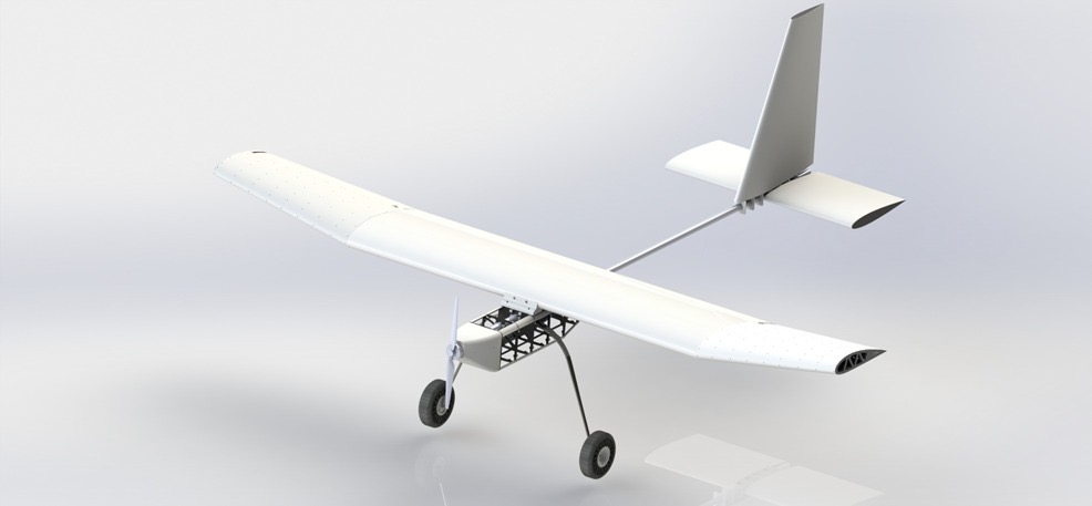
Engineered a lightweight, modular fixed-wing UAV airframe optimized for field serviceability, payload flexibility, and applications in education, surveillance, and agriculture. Focused on aerodynamic efficiency and structural integrity through advanced modeling and analysis.
Technologies
SolidWorksFEACompositesANSYS
Software
SolidWorksFusion 360ANSYS
Contributions
- Led SolidWorks modeling and ANSYS FEA for structural analysis and weight optimization
- Designed key components including wings, fuselage, ailerons, landing gear, and propulsion integration
- Conducted topology optimization and stress testing to ensure durability and efficiency
- Planned material upgrades from ABS to carbon fiber for further weight reduction
Key Features
- Modular wing and fuselage for easy transport and assembly
- Composite-carbon fiber construction for superior strength-to-weight ratio
- Quick-release payload bay supporting multiple mounting configurations
- Field-serviceable components requiring minimal tools
- Aerodynamic optimization for extended flight endurance
- Wing with 10-degree dihedral for enhanced lateral stability; spar-less design tested to support 30kg distributed load
- Fuselage with truss-integrated ABS ribs and PLA corner fillets for rigidity
- Topology-optimized steel landing gear with TPU tires, weighing 2.5kg and handling harsh landings
- Single-engine propulsion system delivering ~10kg static thrust at critical speed of ~100km/h
Challenges & Solutions
- Balancing weight reduction with structural integrity demands
- Developing modular connections that preserve aerodynamic efficiency
- Optimizing composite layup for manufacturing feasibility
- Maintaining precise weight and balance for flight stability
- Ensuring fuselage and wing components withstand substantial forces while minimizing weight
- Topology optimization of landing gear to reduce weight without compromising integrity during impacts
Project Info
Timeline: March 2023 - August 2023 (6 months)
Role: Mechanical Design Engineer
Team: 4-person team
Status: Completed
Client: Near East University Robotics Lab (NEURL)
Impact
Key Results
- Reduced overall aircraft weight by 25% through targeted optimization
- Cut field service time by 40% with modular architecture
- Increased payload capacity by 15% over baseline design
- Passed structural stress tests with a 3x safety factor
Target Audience: Agricultural monitoring and research organizations
Specifications
general
- Wingspan: 3m
- Root Chord: 0.58m
- Tip Chord: 0.38m
- Dihedral: 10 degrees
- Fuselage Length: 1.06m
- Tail Span: 0.94m
- General Length: 2.6m
wing
- Central and wingtip sections with 10-degree dihedral
- 1mm polypropylene (PP) skin, 4mm ABS ribs (planned upgrade to 2mm carbon fiber)
- 3D-printed PLA mounts (~2g each)
- Spar-less design supporting 30kg distributed load
- Total wing weight: 8.5kg
ailerons
- 3D-printed in 4 sections, hollow with internal wafer grate for strength
- No trimming or moment compensation; relies on servomotor torque
fuselage
- 182mm x 178mm ribs from 4mm ABS (~48g each, planned upgrade to 2mm carbon fiber)
- Truss structure for weight reduction
- Bulged sides for secure PP skin fit
- 3D-printed PLA corner fillets (10g each, 114mm)
connector
- 3D-printed with 80% solidity for rigidity
- Tested to handle substantial forces
- Enhanced integrity with closely spaced screws
landing Gear
- Steel frame, 3D-printed TPU tires, PLA rims with wafer design
- Total weight: 2.5kg (optimized to <3kg)
- FEA: Max stress 1200 MPa, y-deformation 159mm
empennage
- Central hub on aluminum pipe with PLA mounts and screws
propulsion
- Motor: Max RPM 7500, Max power 2800W
- Propeller: 22-inch diameter, 8-inch pitch
- Battery: 12s Li-Po (4x 3s in series)
- Performance: Static thrust ~10kg, Critical speed ~100km/h
Software
- SolidWorks
- Fusion 360
- ANSYS